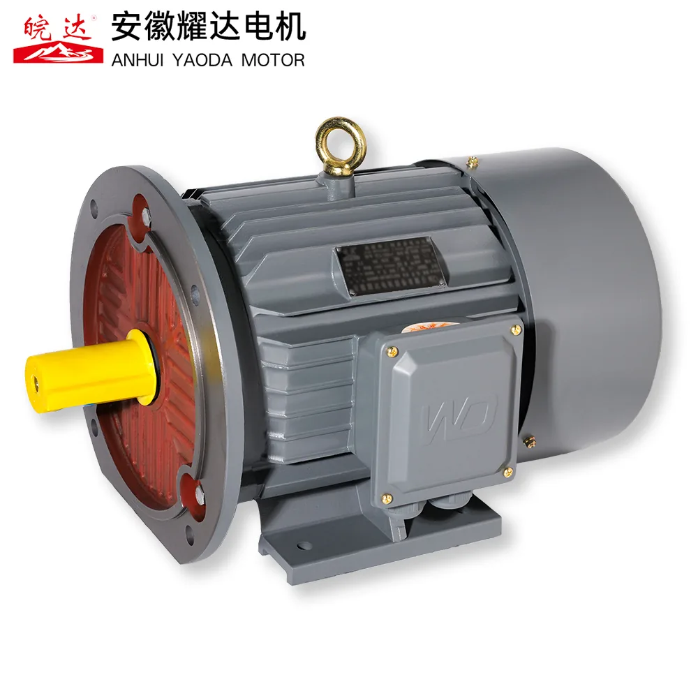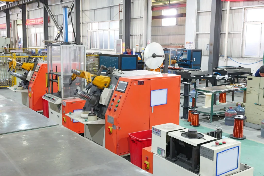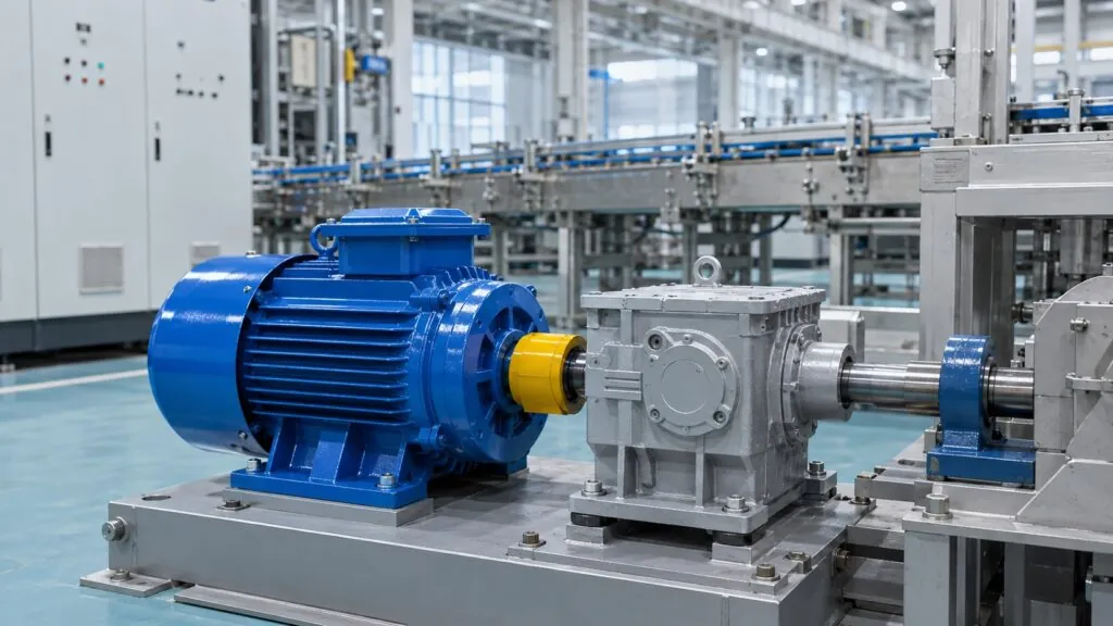






A motor may have run correctly for years and then overheat after a supply or wiring change. When the unit reaches our workshop, the winding can already be damaged while the original cause is still at the supply, terminal box or driven machine.
A three-phase motor on single-phase power will not start and run normally. It may hum, draw excessive current, produce low torque, overheat or trip. Disconnect it after the first sign of trouble and verify the supply and terminal wiring before another start.
A motor that is already turning, or one connected through a capacitor or phase converter, may continue to rotate. That does not make the connection suitable. One live line does not recreate the balanced rotating field for which the three-phase winding was designed, so current distribution, torque and temperature rise become unpredictable.
The important point is practical: a motor can spin and still be in a failure condition. The final decision depends on how it was connected, what happened during the test and what the winding looks like afterward.
Why a Three-Phase Motor Cannot Run Normally on One Phase
A three-phase stator uses three currents separated in time and space to create a rotating magnetic field. A single supply line cannot produce the same starting torque by itself. If the shaft is already moving, the motor may develop enough torque to keep turning, but it may do so with severe current imbalance, reduced output and rapid heating.
A capacitor can shift the current in a temporary circuit and make the shaft move. Its effect depends on the winding taps, capacitance, speed and load. A phase converter can also be used in some installations, but the converter, motor protection and load must be reviewed together. Connecting a capacitor by trial is not a general-purpose conversion method.
This is why a no-load spin can be misleading. The motor may turn freely with the belt removed and then overheat as soon as it has to drive the pump, fan, compressor or gearbox. The load is part of the electrical result, not a separate mechanical question.
How Yaoda Reviews a Motor After Single-Phase Operation
Yaoda starts with the installation record because a replacement motor will repeat the same failure if a missing phase, incorrect terminal link or overloaded driven machine remains. The nameplate alone tells us the intended voltage and connection. It does not tell us what voltage reached the terminals or how many times the motor was restarted.
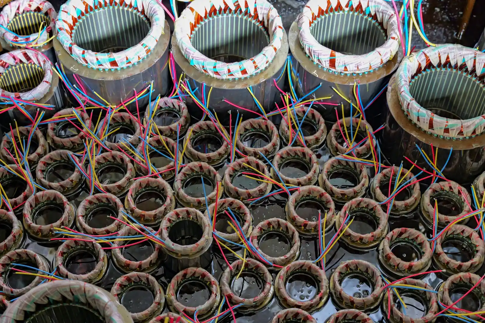
The terminal box is the next point to compare with the nameplate and winding diagram. Photographs taken before the wiring is changed are more useful than a cleaned-up terminal box. Link position, conductor marking, capacitor wiring and any temporary converter connection should all be visible.
Electrical checks then look at the phase paths. Depending on the condition and the customer’s report, a qualified technician may measure winding resistance, insulation resistance to ground, starting current and running current. A controlled run can also show whether temperature, vibration and speed remain normal under the actual or representative load.
Mechanical evidence matters as much as the electrical readings. A bearing fault, seized pump, tight belt or blocked fan can create heat that has nothing to do with the supply. The winding may be the first visible damage, while the original cause sits outside the motor.
Before Calling It a Winding Failure
In the workshop, a burnt winding is an observation, not yet a diagnosis. The more useful question is which condition produced the heat and whether it also damaged the stator core, insulation system or mechanical parts.
Four points are easy to miss during a quick site inspection:
- Only one voltage was measured. Record all three line-to-line voltages while the installation is under a representative load. A reading taken on an isolated control circuit can miss a weak connection or an unbalanced supply.
- A no-load spin was treated as a pass. With the belt or coupling removed, the shaft may turn even when the motor cannot accelerate the real pump, fan or gearbox. Record the load condition during every test.
- The temporary capacitor or converter was removed before inspection. Keep a sketch or photograph of its rating, terminals and conductor route. That circuit explains how the motor was started and which winding paths carried the abnormal current.
- The nameplate was compared with the motor, but not with the field wiring. The intended voltage, star/delta links and terminal markings must be checked against what was actually connected. A replacement motor will fail again if this mismatch remains.
The workshop review also checks whether discolouration is concentrated in one phase path, spread across the winding or linked to a loose terminal. That pattern is compared with the voltage record, current history and insulation tests. A single resistance reading is rarely enough to decide whether the motor was defective, overloaded or damaged by the supply.
Reading the Damage Pattern
No single symptom proves the root cause. The useful approach is to line up the supply record, terminal wiring, winding tests and driven load, then see which explanation fits all of them.
| What was found | What it may indicate | What needs checking next |
|---|---|---|
| The motor hums or stalls after one supply phase is lost | The winding received an unbalanced supply and may have overheated before the protection operated | All three line-to-line voltages, fuse and contact condition, terminal links and protection history |
| The shaft turns only after a push or a temporary capacitor connection | The three-phase motor was not starting normally on the available single-phase supply | Capacitor circuit, winding taps, no-load current, temperature and behaviour under the real load |
| The winding is locally burned or insulation resistance has fallen sharply | Sustained overcurrent and thermal damage may have started inside the winding | Winding resistance, insulation to ground, turn-to-turn evidence and signs of core damage |
| The winding is electrically sound but the motor still overheats | The supply connection, controls or driven machine may be causing the problem | Control voltage, contactor condition, load torque, ventilation, alignment and bearing condition |
↔ Swipe or drag horizontally to view the full table.
Repair or Replace?
A sound winding after a wiring error may need the connection corrected and a controlled retest, not a new motor. Localized damage may be suitable for a targeted repair or rewind if the mechanical condition is acceptable and the cause has been corrected. Extensive burning, low insulation resistance or core damage usually makes replacement the more realistic route.
The decision should not rest on the price of a rewind alone. The frame, shaft, flange, winding data, duty, protection and downtime all affect whether a repair is sensible for the application.
For a closer assessment of ground faults, short circuits and winding damage, use Yaoda’s three-phase induction motor winding fault guide.
What a Photo Cannot Prove
A photograph can show discoloured insulation, a loose link or a damaged terminal. It cannot show whether the phase loss came from the utility, a fuse, a contactor or a wiring mistake. It also cannot show whether the motor ran overloaded for several minutes before it was stopped.
A single photograph is therefore not enough to establish the failure cause. The terminal-wiring photo is valuable when it is matched with voltage readings, trip history and the condition of the driven machine.
If the Site Has Only Single-Phase Power
For a small, fixed-speed machine, a purpose-built single-phase motor is often the simplest choice. It is designed to start and run from that supply without relying on a three-phase winding connected through a temporary capacitor.
Where speed control is required, a drive rated for single-phase input can be used with a compatible motor. The motor insulation, cooling, duty and cable arrangement still need to suit the drive. The input rating of the drive is a separate requirement from the output rating of the motor.
A phase-conversion system may be suitable for some three-phase loads, but it must be sized for starting current and checked for voltage balance. For an engineered variable-speed arrangement, review Yaoda’s YVF2 variable frequency motor range together with the converter and protection scheme.
Before selecting a replacement, use the three-phase motor voltage by country guide to check the destination voltage and frequency. The final setting should always be confirmed at the installation.
What to Send with a Failed Motor
For a review, send the evidence in one package rather than a winding photo on its own:
- Nameplate and terminal-box photos taken before any wiring was changed.
- All three line-to-line voltages, supply frequency and the condition of fuses or contacts.
- Protection settings, trip history and how many times the motor was restarted.
- Details of any capacitor, phase converter or variable-frequency drive used.
- The driven machine, load condition and whether the fault occurred at start or during operation.
- Winding resistance and insulation-resistance results where these tests were performed safely.
- Dates of temporary repairs, replacement parts and any previous overheating incidents.
- The corrected application data: voltage, frequency, starting method, duty, environment, mounting and quantity.
State the corrected application too. Anhui Yaoda Motor Co., Ltd. manufactures induction motors in Chuzhou, Anhui, China, and can review the returned unit against its winding specification and routine test record.
Ask Yaoda to Review the Failure
Send the panel readings, terminal wiring, test results, driven-load information and operating conditions together. The factory review can then focus on the actual failure sequence rather than the damaged winding alone.